Learn about the basics of circuitry and get hands-on experience!
Binary
Computers use a complex arrangement of ones and zeroes to transmit information. This is called binary. A single digit, be it a 1 or 0, is called a bit. Combine 8 of these together, and now it is called a byte. A byte is a standard size of memory used by your computer. In binary, each position from right to left is worth double the previous value. Taking the sum of the positions that are represented by a 1 will give us the value in a way we can understand.

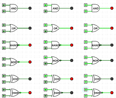
Understanding Logic Gates
If we take a closer look a circuit board, we can see they are made from thousands of logic gates. These are simple structures that will output a 1 or 0 depending on its inputs. Several basic gates include
Combining Logic Gates
We can combine individual logic gates together, in order to form complex circuits capable of completing large tasks. For example, a few NAND gates and inverters combined correctly will create a Half-adder circuit, which is widely used in many machines. This circuit adds 2 bits together, A and B, and will output their sum and carried value as 2 bits, if necessary.

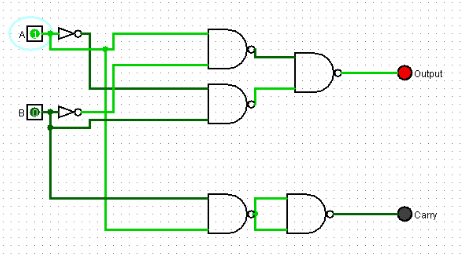
Now its your turn!
Logism is a free piece of software used to digitally design circuits. It has a very intuitive interface and can run on almost any computer. Logism can be downloaded from:
Getting Started with Logism
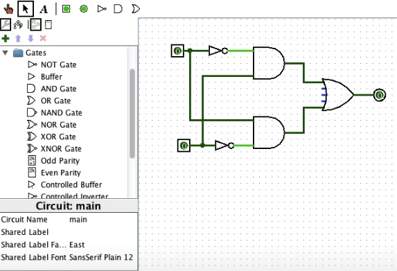
Once downloaded and launched, users will be greeted with this screen, minus the overlay. Logism will be broken down into 4 main sections.
The first section in the top left gives us a few ways to interact with our project. The hand allows users to toggle buttons or other input devices within the circuit. The cursor allows the user to click and drag gates to edit the circuit. The A will allow users to place down text. Finally, the last buttons can be used to quickly place down some commonly used devices.
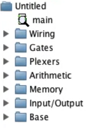
Moving onto the second section, this area contains folders that neatly sort components by function. Each of the folders contain a number of pieces. This is where you will source parts to build your circuits.
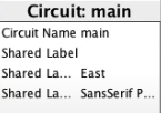
Area 3 will highlight information about whatever piece you have selected. In this case, it is the entire circuit itself. In other cases, such as if viewing a logic gate’s information, many settings can be modified here. This includes the number of input channels, the name of the gate, and the direction it is facing.
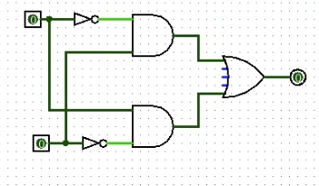
Finally, area 4 is the stage where you will do the building. You can drag pieces from area 2 onto the stage, and then connect them by drawing a wire from one piece to another using the cursor. Once you are happy with your circuit, the save button is located just above section 1 under the file tab.
